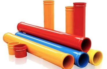
Flow in a pipe
Fluid flow in a pipe depends on the pressure applied, the radius of the pipe and
the viscosity of the fluid. Para um fluido newtoniano, the flow is directly proportional to the
viscosity, que é uma constante. Para um fluido não newtoniano com uma viscosidade que depende
3
sobre a tensão de cisalhamento, como rejuntes e concretos, the flow rate is a complicated function
of the viscosity.
A viscosidade () de um fluido é a proporção da tensão de cisalhamento () para a taxa de cisalhamento (̇):
= / ̇. This definition is convenient for Newtonian fluids, and certain non-Newtonian
fluidos. In other cases, however, an engineering approach to the description of a fluid can
simplify the analysis. For instance if the fluid is approximated as a power law fluid, it can
be described by Eq. 1 where τ is the shear stress, K the power law consistency index, ̇
the shear rate, n the power law exponent:
n = Kγτ [ 1]
The corresponding velocity profile in a circular pipe is then given by equation 2 [4]:
1 1/
2
(3 1) ( ) 1 ( ) ( 1)
n
p p
Qn r v r
p Rn R
+ + = − +
[ 2]
where v is the fluid velocity as a function of the radial position, r , in the pipe, Q the
volumetric flow rate, and Rp the pipe radius. The fluid power law consistency index, K,
can be calculated using the following equation 3 [4], which requires a pressure drop
measurement over a certain length:
3 3 1/
2
n
n
p
P Q K R
L p
∆ − − =
[ 3]
where ∆P is the pressure drop, and L the distance between the pressure sensors. o
exponent n and the factor K could also be determined via equation 1 from rheological
measurements of the fluid through a rheometer if available. But equations 2 e 3 could
also be used to determine n and K from the pipe flow, in absence of a suitable rheometer.
The shear rate at the wall surface is calculated using the following equation [5, 6]:
3
3 1 ( ) p
p
n Q r R
n R γ
p
+ = = [ 4]
The local shear stress is
τ = ∆rP L / 2 [ 5]
The equations 1 through 5 describe flow of a homogenous fluid in a pipe.
Contudo, concrete is more a complex fluid because it contains aggregates with a wide
4
range of sizes. These aggregates interact with the pipe walls and each other, creating
inhomogeneities in the fluid. Thus, concrete flow in a pipe typically occurs in three layers
or regions [5, 6] as shown in Figure 1:
• Slip-layer or lubrication layer,
• The shearing region or layer, e
• The inner concrete or layer, also referred to as a plug flow layer
The thickness of the slip layer depends upon the tribology of the material adjacent
to the pipe material. Tribology is “the science and technology concerned with interacting
surfaces in relative motion, including friction, lubrication, vestir, and erosion” [7]. o
thickness of, and the velocity profile within, the shearing layer depends upon the
viscosity and the yield stress. The thickness of the inner layer depends upon the yield
estresse.
The composition and physical characteristics of each layer are difficult to know.
Their characterization requires the extraction of material from disparate regions. o
slip/lubrication layer contains mainly cement paste and possibly very small sand particles
[8], while the inner layer contains coarse aggregates. Also, the diameter of the inner layer
or the thickness of the slip-layer is unknown. It is conceivable that prediction of concrete
flow in a pipe will need the characterization of each of the layers.
Figure 1: Profile of flow of concrete in a pipe [6]
2.2. Slip-layer
Several research groups have investigated the slip-layer of concrete flow in a
tubulação de. Choi et al. [5, 6] measured the thickness of the slip-layer using an Ultrasonic
Velocity Profiler (UVP) in pumping circuits using industrial equipment and found that
there is a 2 mm thick layer along the inner surface of the pipe. Contudo, the layer
thickness could vary depending on the mixture proportions and the pipe configuration.
Kaplan [9] reported that the flow of concrete in a pipe is mainly related to the
viscosity of the slip-layer and that its properties could be measured by tribometry. He
found that the correlation between the properties of the bulk material as measured in a
5
rheometer and the properties of the slip-layer was weak. Jacobsen et al. [10] showed by
using colored concrete that the velocity profile of the concrete resembled that of plug
flow in the pipe center, and non-moving slip-layer, similar to that shown in Figure 1.
Kwon et al.[11, 12] measured the rheological properties of concrete before and
after pumping while monitoring the pressure and flow rate and found that while there was
no correlation between bulk concrete rheological properties, por exemplo, viscosity and yield
estresse, and flow rates, there was a strong correlation between properties of the slip-layer
and flow rates. Thus they deduced that the slip-layer is the determining factor to
predicting that concrete will flow in a pipe. They then proceeded to develop a tribometer
that is a coaxial rheometer with a smooth bob made of steel or covered with rubber to
simulate the slip-layer of the pipe.
Ngo et al.[13] observed that the slip-layer is between 1 mm para 9 mm thick, por
visualizing the material flow in the rheometer. He analyzed the layer and found that it
contained sand with a particle size less than 0.25 mm. This would imply that there is a
migration of coarse aggregates from near the wall to the center of the pipe where the
shear rate is lower than that found near the walls.
2.3. Pumping pressure
Another factor in pumping is the pressure applied to the material to move it
through the pipe. Rio et al. [8] showed with a large number of pumping tests that the
relationship between the pressure of the pump and the flow rate of the material is linear:
P k kQ = +1 2 [ 6]
onde 1 k and 2 k are two empirical parameters that depend on the material and other
experimental conditions. Rio et al. concluded that the two parameters can be used to
characterize a specific mixture. Rio et al. [8] advocated that the knowledge of these
parameters for a specific mixture and pumping circuit could be used as a quality control
tool to ensure that the applied pressure is sufficient to ensure the desired flow rate.
Feys et al. [14] established an empirical relationship between the plastic viscosity
of the concrete at a shear rate of 10 s-1 and the pressure gradient in a pipe. If the pressure
gradient is too low, the material will not move through the pipe. Feys mentioned two
issues relevant to the prediction of flow in a pipe: 1) the slip-layer influence is very
important, but it is not well understood and is difficult to measure; 2) the shear rates in
the pipe are spatially and temporally varying. One solution for the effect of the slip-layer
would be to measure its rheological properties, if it could be isolated and extracted.
Modeling of the flow in a pipe might help resolve the second issue. Feys et al. [14] Além disso
observed that the pumping of self-consolidating concrete (CCS) requires a higher
pressão, while the yield stress is almost zero, but the plastic viscosity is higher than that
for normal concrete. This could be due to the slip-layer (Figure 1) that would require a
higher shear stress at the same shear rate due to the increased viscosity.
- PÁGINA INICIAL
- Quem somos
- PRODUTOS
- Tubo de liga de aço
- Flange de tubo de aço
- Redutor de tubos de aço
- Cotovelo de tubo de aço
- Ajuste do tubo ranhurado
- Bomba de concreto e peças
- Tubulação de bomba de concreto
- Cotovelo de bomba de concreto
- Braçadeira de bomba de concreto
- Curva de bomba de concreto
- Flange da bomba de concreto
- Concreto colocação Boom
- Peças da bomba de concreto
- Pistão de bomba de concreto
- Mangueira de borracha de bomba de concreto
- Bomba de concreto placa do desgaste e usar o anel
- Cilindro de bomba de concreto
- Gaxeta da bomba de concreto
- PUTZMEISTER
- SCHWING
- Pilhas de parafuso de chão
- CLIENTE & EXPOSIÇÃO
- CONHECIMENTO TÉCNICO
- ENTRE EM CONTATO CONOSCO


Você deve ser logado para postar um comentário.